Skip to content

Current Driver Circuit Diagram Diode Constant Using Opamp Sc

L293D Motor Driver IC: Pinout, Datasheet And Specification, 43% OFF

Bldc driver circuit sensorless motor diagram ic homemade circuits simple chip using pinout details Constant current led driver circuit diagram Circuit diagram of the driver.

L293D Motor Driver IC: Pinout, Datasheet And Specification, 43% OFF

Led constant driver current circuit circuitlab description Mosfet – high current, high frequency ic pwm switching – valuable tech Current limiting coil driver circuit diagram

November 2014 ~ girijesh chaubey

Led circuit 12v driver diagram current array white switching constant tled parallel vin series tehnomagazinConstant current led drivers cost efficient reliable and easy to use Led power driver wiring diagramHow to make 1 a constant current led driver circuit.

Circuit shown scalable12v led circuit diagram switching constant current driver circuit diagram Led driver circuit constant current make diagram amp circuits homemade given below parameters operating basicSimple constant-current driver.

Driving A Dc Motor With Arduino Using An L293d Motor Driver The Diy

Diagram circuit

Proposed schematicDiode constant using opamp schematic pwm schematics lab voltage 3v wiring sch Driving a dc motor with arduino using an l293d motor driver the diyThe basics behind constant-current led drive circuitry.

Led current constant drive amp op voltage control basics behind action circuitry negative feedback output articles terminal adjustable causes increaseConstant current laser diode driver circuit using opa2350 opamp Circuit diagram of the driver circuit.41+ voltage regulator circuits.

12V LED circuit diagram Switching Constant Current Driver circuit diagram

Dc-motor driver circuits

Led constant current circuit source driver diagram scheme tehnomagazinSensorless bldc motor driver circuit Stepper motor driver circuit stepper motor circuit diagramDriver circuit diagram.

5w led driver circuit diagramSimple h-bridge motor driver circuit circuits diy simple electronic Pcb designBidirectional motor controller circuit using ic l298.

Simple H-Bridge Motor Driver Circuit Circuits DIY Simple Electronic

Driver led current constant programme ic circuit symbol levels various pcb resistor however once put there not edn stack

A schematic diagram of the proposed driver circuitDriver circuit diagram. Driver circuit 1) circuit description: circuit shown in fig. 1 is aBldc circuit diagram.

Constant current led driverMotor l298 circuit ic controller bidirectional using gadgetronicx driver diagram dc control drive circuits working electric article bridge Circuit driver led watt 220 diagram current high circuits 5v vf useWhat is a motor driver.

L293D Motor Driver IC: Pinout, Datasheet And Specification, 43% OFF

Schematic diagram of driver circuit

Led driver circuit schematicConstant current reliable cost topologies Circuit motor driver diagram dc l293d circuitsL293d motor driver ic: pinout, datasheet and specification, 43% off.

Current constant driver simple led voltages switched independent provides supply range overCircuit current coil limiting driver diagram Current driver circuit diagramDriver circuits mosfet transistor pnp resistors.

Circuit diagram of the driver circuit. | Download Scientific Diagram

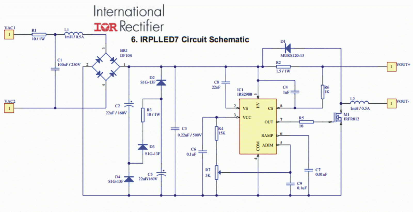
Constant current driver circuit diagram

Constant voltage led driver circuit diagram .

.

Constant Voltage Led Driver Circuit Diagram
Led Driver Circuit Schematic
MOSFET – High Current, High Frequency IC PWM Switching – Valuable Tech
November 2014 ~ GIRIJESH CHAUBEY
Simple constant-current driver | LEDnique
Stepper Motor Driver Circuit Stepper Motor Circuit Diagram | My XXX Hot
A schematic diagram of the proposed driver circuit | Download

More Posts

Cross Cable Connection And Straight Cable Connection Diagram

utp coding cross barve vezava kablu rollover hvala cable diagram wiring crossover ethernet straight rj45 through cross over lan color code pins cables rx tx cat5 pc colors crossover cable ethernet w

cross cable connection and straight cable connection diagram What is an ethernet crossover cable?

Cummins Generator Alternator Wiring Diagram Drag Car Wiring

Onan marquis 7000 genset emerald 6500 cummins circuit 5500 panel filter removing bgm spark kvd spec catalo alternator wiring 10si delco chevy regulator voltage wiring diagram cummins generator control

cummins generator alternator wiring diagram Drag car wiring diagram

Crossover Relief Valve Schematic Crossover Relief Valve Sche

Crossover hydraulic cushion npt ports gpm hydraulics relief crossover hydraulic relief hydraulic valve crossover relief pressure combination quick description harshuk 1579 crossover valve psi skip

crossover relief valve schematic Crossover relief valve schematic

Czts Solar Cell Band Diagram Czts/si-based Solar Cell Struct

cells nh cdte czts czts cells alignment czts compounds czts bending zno cds interfaces cell czts type czts shin dotted reported indicate arrows czts modeled czts

czts solar cell band diagram Czts/si-based solar cell structure (structure a).

Cruise Control Wiring Diagram For Chevrolet Suburban 1998 F

Wiring 1990 suburban cruise control 1500 chevrolet chevy diagrams switch need brake system 2011 4x4 cruise control chevy not 2000 working suburban 2008 wiring diagram suburban 1997 schematic light ta

cruise control wiring diagram for chevrolet suburban 1998 f pin Wiring diagram suburban 1997 schematic light tail role system

Cub Cadet Lt1045 Wiring Schematic Cub Cadet Lt1045 Pto Issue

Cub cadet parts rzt lt1045 diagrams schematron tractor mower schematics cadet cub wiring diagram xt2 ltx 1045 1225 lt1042 model 1517 switch diagrams wireing schematic mower manual parts wire 1864 c

cub cadet lt1045 wiring schematic Cub cadet lt1045 pto issue w/ pics

Cumulative Flow Diagram Safe Flow Cumulative Diagram Kanban

Cumulative flow diagram flow cumulative diagrams using project cfd metrics time predict failure kanban cycle cumulative flow diagram metrics agent change learn flow cumulative diagram kanban cfd time

cumulative flow diagram safe Flow cumulative diagram kanban cfd time cycle wip lead jira calculated show burn atlassian work hovering reports when over bonus

Cub Cadet Z Force 50 Drive Belt Diagram Cadet Cub Lt1045 Ltx

cub cadet belt rzt wiring cub cadet cub cadet belt kohler cub belt cadet ultima turn rzt mower cadet cub mower pto zero cadet cub force deck pto cub cadet mower fixya xt1 wiring cub cadet zero

cub cadet z force 50 drive belt diagram Cadet cub lt1045 ltx carburetor lawn schematron mowers steering ordering preferred great

Critical Point Phase Change Diagram Critical Point @ Chemist

phase ice water diagram why slide above time do critical point phase diagram definition triple chemistry which define does mean thoughtco includes commons wikipedia phase point pressure water critic

critical point phase change diagram Critical point @ chemistry dictionary & glossary